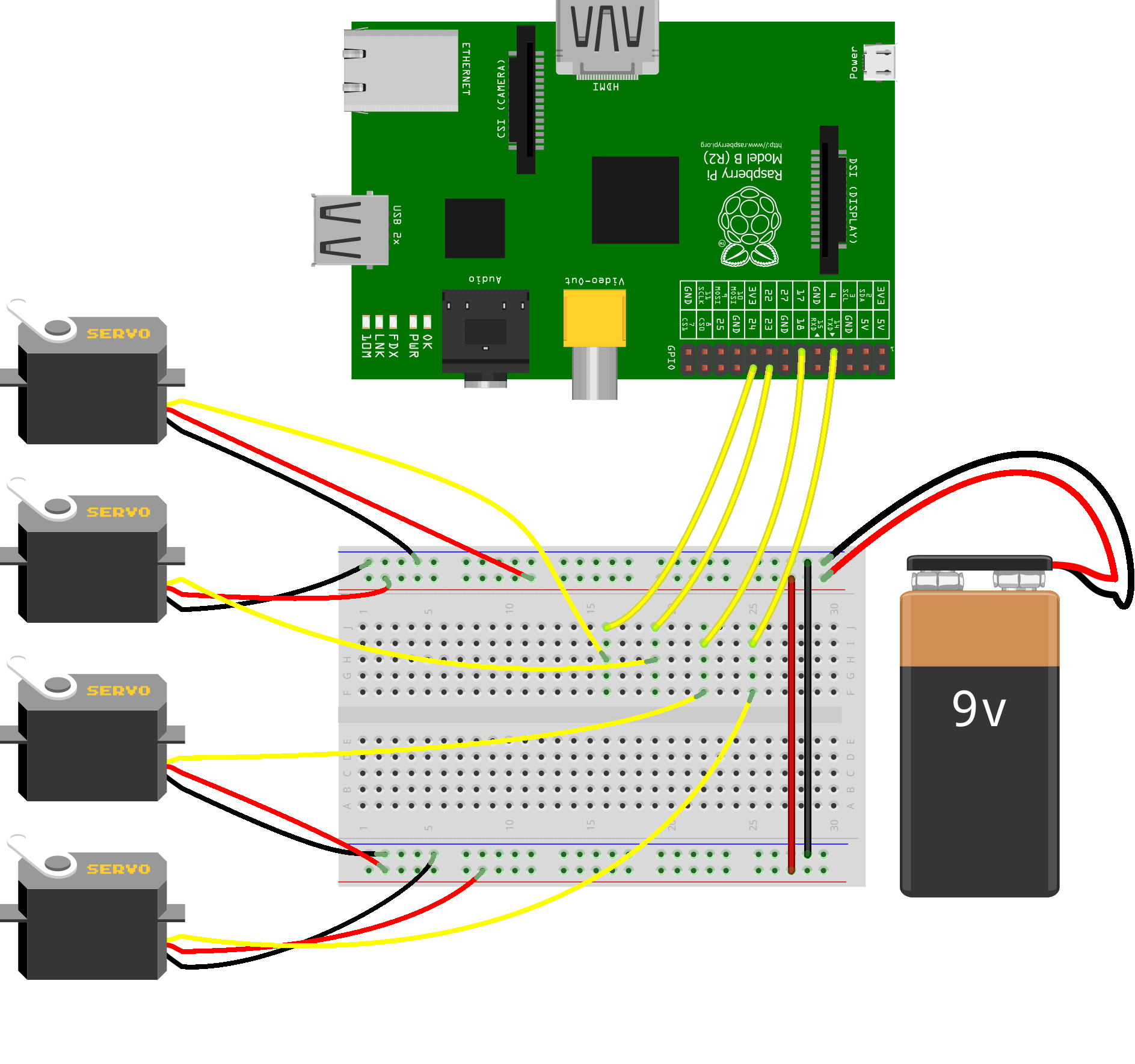
The servo controller schematic is a unique engineering feat that can be used to control the motion of motors and other machinery. It consists of a circuit board and several components that work together as a single unit to control the motor’s position and speed. This type of controller is used in a variety of applications, from robotic arms to 3D printers, to precise medical equipment, and more.
At the heart of the servo controller schematic is its circuit board, which contains an integrated circuit (IC) and several peripheral components. Depending on the specific application, the IC can be programmed to react to various signals, allowing for precise control over the motor’s speed and direction. It also contains a space for connecting different components like sensors, transistors, and other components to customize the system’s performance.
The servo controller schematic is a powerful tool that allows users to finely tune the motion of their motors and other machinery. With its precise and reliable control over the motion, users can achieve maximum efficiency when operating their machines. From automating robotic arms to safely operating 3D printers, this type of controller has become an invaluable asset for many industries.
Servo Motor System Controller Under Repository Circuits 22818 Next Gr

Brushed Dc Servo Motor Driver Circuit Ideas I Electronic Diy Projects Robotics

A Control Mode 1 Schematic Diagram For In Vitro Robotic Experiments Scientific

How To Control Servo Motors With Arduino Complete Guide

Pic Servo Controller Northwestern Mechatronics Wiki
Ntroller Circuit Diagram And Working Principle 1 Chegg Com

Control Circuit For Controlling Dc Servomotor Adjustment And Feedback Scientific Diagram

Simple Servo Controller

4 Channel Rc Servo Controller Board Schematic Png Electronics Lab Com

Servo Motor Circuit Page 3 Automation Circuits Next Gr

Lab 21 Servo Motor Control Embedded

Position Control Servo Valve Matlab Simulink

Servo Motor Driver Circuit Using Ic 555 Gadgetronicx

How To Use Servos On The Raspberry Pi Circuit Basics

Hobby Servos

Servo Motor Systems Worksheet Analog Integrated Circuits

How Rc Servos Works

Building A Hobby Servo Controller Part 1 Blog Raspberry Pi Projects Element14 Community

Arduino Servo Motor Control Tutorial With Circuit Diagram And Code
