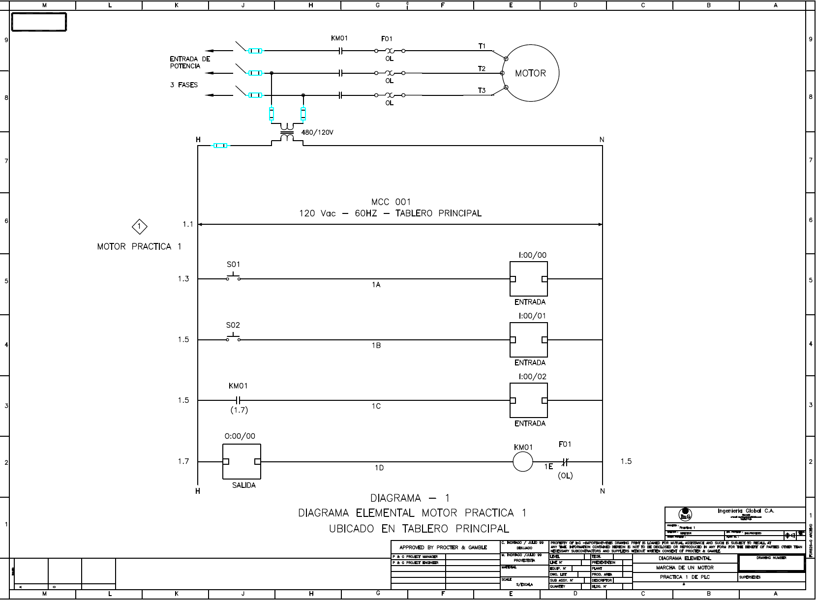
Safety measures for electrical systems are essential in order to maintain the health and safety of those who work with them. This is why the American National Standards Institute (ANSI) has developed standards for electrical schematic symbols. These symbols allow for the efficient communication of complex electrical systems and can help reduce the potential of errors and potential hazards.
Understanding the ANSI standard electrical schematic symbols is key to correctly interpreting electrical information and interpreting a system's operation. These symbols provide a visual representation of the components found within an electrical circuit and are especially useful when used to describe the process or an operation. By using standardized symbols, technicians can quickly make sense of a system’s operation, anticipate potential problems, and work toward solutions.
The usage of ANSI standard electrical schematic symbols is a crucial part of effectively designing and troubleshooting control systems. An accurate understanding of these symbols allows electricians to quickly identify components, understand the relationship between them, and solve problems more efficiently. Plus, the standardized schematics provide a uniform visual language within the industry, ensuring better communication across all stakeholders. It also allows for faster development of controls and systems, helping to increase productivity as well.

Blueprint Language

Electronic Component Lists And Schematic Symbols Free Online Pcb Cad Library
Nema And Iec Schematic Diagram Comparisons Mz081001en
Electrical Plan Symbols One Line Medium Voltage Low Miscellaneous Identification Grounding Lu

Electronic Circuit Symbols Component Schematic Electronics Notes

Smartdraw On Twitter Symbols In Circuit Diagrams And Schematics Are Covered By A Variety Of National International Standards Iec Ieee Ansi Here Just Few Common Electrical

Draftsight Electrical Symbol Library Free
Nema And Iec Schematic Diagram Comparisons Mz081001en

Back To Basics Refresher Essential Electrical Symbols Ec M
Nema And Iec Schematic Diagram Comparisons Mz081001en

The Most Common Control Valve Symbols On A P Id Kimray
Typical Electrical Drawing Symbols And Conventions

Electrical Symbols Ieee Std 315 1975 Quick Reference Only

How To Make A Single Line Diagram

Solid Edge Wiring Design

Intro To Relays 2 Ansi Ieee Relay Numbers

Electrical Symbols Ieee Std 315 1975 Quick Reference Only

Electrical Drawings Control Real English
