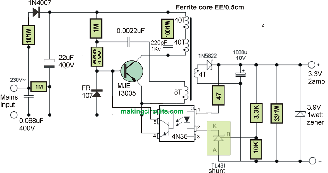
24 volt SMPS (switched-mode power supply) circuit diagrams are essential for the efficient and reliable operation of a variety of electronic devices. They are used to deliver low-voltage, high-frequency switching power from an AC or DC source to devices that require stable power without the need for additional components. This can significantly reduce the size and cost of the circuits.
The 24 volt SMPS circuit diagram consists of several primary components: the rectifier, the bridge rectifier, the main circuit, the main output transformer, the secondary output transformer, and the switch. The rectifier is generally the component that takes raw voltage and converts it into a more stable, usable one. The bridge rectifier is often used in conjunction with the rectifier to ensure even distribution of the voltage throughout the entire circuit. The main circuit is what directs the power to the output, while the main output transformer is responsible for transforming the power from its raw form into a more usable form.
Finally, the switch is used to control the on/off power flow in the circuit. This can be both manual and automatic, depending on the specific application. In the case of 24 volt SMPS circuits, the switch is typically automated and programmed to turn off after a certain amount of time or when the circuit reaches a certain level of voltage. When all these components are properly combined, they create an efficient and reliable power supply system that is ideal for powering many devices.

13 8v 40a Switching Power Supply

35w Switching Power Supply Circuit Having A Set Top Box Output Of 5 Under Circuits 58748 Next Gr
120 W 24 V 3 5 A 12 Smps Demonstrator With Idp2303

24v 2 5 Amp Single Output Switching Power Supply

Switching Power Supply Page 6 Circuits Next Gr

12v To 24v Dc Converter Power Supply Circuit Diagram

Circuit Diagram Of Smps Oscillator Scientific

24v 2a Dc Power Supply Circuits
Application Note Evaluation Board 300w General Purpose Wide Range Smps

24v 18a Switch Mode Power Supply Circuit Uc3825 Smps Electronics Projects Circuits

3 3v 2amp Smps Circuit For Leds

Reverse Engineered Schematics

Switching Power Supply Circuits Next Gr

9 Ways To Build 24v Power Supply Circuits With Easy Parts

12v 24v 1 Amp Mosfet Smps Circuit Homemade Projects

9 Ways To Build 24v Power Supply Circuits With Easy Parts
Reference Designs

Ro Smps Pcb Applicable Industry Commercial Capacity 60w 24v 2 5amp Rs 8 Piece Id 21130221791

