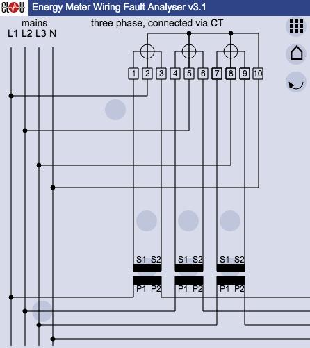
Most of us are familiar with electricity and the processes of wiring; however, few understand the complexities that come with wiring diagrams for CT metering. A wiring diagram for CT metering is an essential tool for any electrician, engineer, or other involved parties to properly install and maintain any electrical system with a current transformer. These diagrams provide detailed visualization of all electrical connections to ensure the safety and accuracy of the system.
CT metering is a process of managing the electrical current in a system by utilizing current transformers to measure the total amount of current in a circuit. The current transformer will take a large amount of current, such as the amount that comes out of a service panel, and convert it in to a much smaller amount that can be used for metering purposes. A wiring diagram for CT metering reflects those connections and allows for proper installation, maintenance, and safe operation of the system.
Accuracy and safety are paramount when it comes to CT metering, and a wiring diagram serves as an invaluable tool in making sure everything is working correctly. It is important to always use the most up-to-date wiring diagram when changing any component of the system, as outdated diagrams could lead to inaccurate readings or even electrical fires. With this in mind, anyone who needs to use a wiring diagram for CT metering should always double check to make sure they are working with the most recent version available.

Combined Ct Metering Chamber And Hdco 3 Phase 400 V Up To 630 A Rated Lucy Electric
Electric Revenue High Voltage Metering
Ct And Pt Connection Diagram Explained Etechnog

Services Support Faq Why Does My Power Meter Dpm C530a Series Show Negative Kw Readings Delta
Instrument Rated

Power Monitoring Single 3 Phase And Dynamometer
3 Phase Meter With Connection Via Ct Pulse Or Modbus Rs485 Output Outpu

Resources For Electricians Roughrider Electric Cooperative Inc

Cur Transformer Electricity Meter Wiring Diagram Kilowatt Hour Three Phase Electric Power Png Clipart Angle Area

Electricity Theft Neutral Disconnect Cur Transformer Ct Scientific Diagram

Wiring Diagrams Bay City Metering Nyc

Wiring New With 3 Phase Service Doityourself Com Community Forums
Residential Watt Hour Meter

47 Ways To Wire Your Power Meter Wrong Kele Com

Wiring Diagrams Bay City Metering Nyc

Make The Most Of Portable Meter Test Clou Global
Cur Transformer Wiring Diagram Instructions

Em537 Ct 3 Phase 4 Wire Energy Meter Modbus Electricity Din Rail Kwh Aliexpress Tools
How To Properly Short A Ct Shorting Block Schneider Electric Usa


