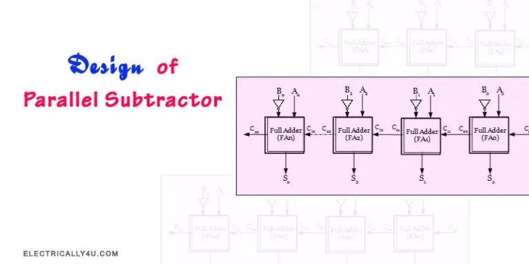
When it comes to technology, all electrical engineers and hobbyists alike, understand the need of a 4 Bit Parallel Adder Circuit Diagram. This circuit diagram is highly useful in designing complex electronic circuits and systems. It allows electrical engineers to efficiently represent and understand the operation of a circuit. A 4-bit parallel adder circuit is composed of four full-adder logic gates each with its own specific output.
A 4-Bit Parallel Adder Circuit is an essential tool for quickly and accurately adding binary numbers. This is especially important when designing or constructing electronic devices or systems that require complex calculations. The circuit is typically set up with two inputs, one carry-in bit, and four output bits. When a signal is applied to the inputs, the circuitry works together to calculate the output depending on the input value.
For anyone in the engineering field, having the necessary knowledge and understanding of the 4 Bit Parallel Adder Circuit Diagram is essential. Not only does it allow for more complicated digital components to be designed, but it can also be used during digital simulation. By understanding the principles of this circuit, electrical engineers are able to better plan and create efficient, accurate, and reliable designs. With a clear understanding of the 4-bit parallel adder circuit diagram, they will be able to make sure that the components they are designing are capable of reaching the desired outcome without having to make unnecessary changes.

A Bit Parallel Ripple Carry Adder In Serial B Scientific Diagram

N Bit Parallel Adders 4 Binary Adder And Subtractor
9 Four Bit Adder Mr Bridger S Web Page

What Is Parallel Binary Adder 2 Bit And 5 Electronics Coach

N Bit Parallel Adders 4 Binary Adder And Subtractor

Design Of Parallel Subtractor

Cs1104 Computer Organisation Lecture 6 Combinational Circuits Design Methods Arithmetic Ppt
9 Four Bit Adder Mr Bridger S Web Page
Solved Create A Circuit Diagram For 4 Bit Parallel Chegg Com

Ic Adder Chip Under Repository Circuits 45942 Next Gr

N Bit Parallel Adders 4 Binary Adder And Subtractor

Explain Block Diagram For 4 Bit Parallel Adder Computer Engineering
3 2 4 Bits Reversible Parallel Adder With The Cascade Of Four Scientific Diagram

Parallel Subtractor Electrical4u

Vhdl Code For 4 Bit Adder Subtractor

4 Bit Full Adder Using Logic Gates In Proteus The Engineering Projects
Task 7 Implementing A 4 Bit Parallel Adder Using Chegg Com

Parallel Binary Adders

Figure5 Parallel Adder 4 Bit Ripple Carry Block Diagram Scientific

