The binary subtractor is an important circuit in the field of digital electronics. It is used to subtract two binary numbers and is often a precursor to advanced operations such as addition and multiplication. As a result, having a good understanding of their design and functioning is essential to those interested in electronic and computer engineering.
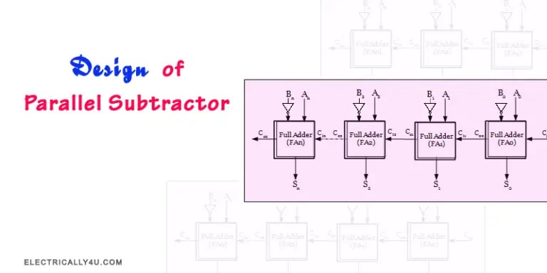
The basic architecture of a 4 bit binary subtractor consists of four full adders, which combine three inputs and produce two outputs. In addition, it also has multiplexers, which are used to select the right input values during the subtractions process. For example, when subtracting two numbers, the first multiplexer will select the smaller number while the second multiplexer will select the larger one. Finally, the circuit also needs logic gates to ensure the correct operation of the subtractor.
Overall, the 4 bit binary subtractor is a powerful digital circuit with many uses. It can be used for simple arithmetic operations such as subtraction and can also be adapted for more complex operations. With a good understanding of its internal architecture, developers can exploit its potential for a variety of applications. From formulating financial models to processing digital signals, the 4 bit binary subtractor is an essential tool for digital electronics.

Half Adders And Full

Digital Arithmetic Circuits

What Is The Logic Diagram Of 4 Bit Subtractor Quora
How To Make A Truth Table For 4 Bit Parallel Adder Quora

Digital Logic

N Bit Parallel Adders 4 Binary Adder And Subtractor

Binary Subtraction Truth Table Working Designing Rules

Design Of Parallel Subtractor

Binary Subtraction With Two S Complement

How To Design A Four Bit Adder Subtractor Circuit Ee Vibes

Chapter 11 Laboratory Experiment Ppt Online

Figure 16 7 Shows A Four Bit Binary Adder Subtractor Circuit Configured Around Parallel Type Number 7483 And Quad Two Input Ex Or Gate 7486 The Arrangement Works As An

Decimal Or Bcd Adder Javatpoint

What Happens When The Sum Of A 4 Bit Adder Is Greater Than 15 Quora

Module Ii Binary Subtractor Ppt Online

Full Subtractor Javatpoint
2 4 Binary Adder Subtractor Addition And Subtraction Are Two Basic Arithmetic Operations That Must Be Performed By Any Dig

Exploreroots Parallel Subtractor Borrow Propagate Look Ahead

4 Bit Binary Adder Tinkercad

Ic 4008 4 Bit Binary Full Adder Build Electronic Circuits
