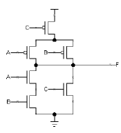
XOR gates (also known as exclusive-or gates) are logic gates that are often used in digital circuits. XOR gates are used to produce a specific type of output when two inputs are received; if both inputs are "1" or "0", the output is "0". But if the two inputs differ, then the output is "1". This makes XOR gates particularly useful for performing arithmetic operations.
In order to create a CMOS XOR gate circuit, one must first understand the basic principles of CMOS circuitry. CMOS stands for Complementary Metal-Oxide-Semiconductor, and is a type of circuit technology used to make microchips; a CMOS gate is a logic gate that is constructed on such a microchip. To create a CMOS XOR gate, one typically begins by using a method called “static CMOS”. This involves the use of a series of MOSFET transistors arranged in a specific configuration; the transistors act as an electronic switch that can be activated and deactivated based on the input signals. The CMOS XOR gate will then produce a logical output when two different inputs are received simultaneously.
Finally, the CMOS XOR gate circuit diagram should be studied in order to provide a visual representation of the logic operation. This can be done by drawing the schematic of the circuit, including the various interconnections between the components. Once the diagram is created, its function can then be tested with a digital simulator to see if it produces the expected output when given certain inputs. By understanding and creating a CMOS XOR gate circuit diagram, one can quickly and easily design logic circuits for any application.

Bipolar Xor Gate With Only 2 Transistors Details Hackaday Io

Cmos Based Carbon Nano Pass Transistor Logic Integrated Circuits Nature Communications

Xor Gate Using Pass Transistor Logic Digital Cmos Design Electronics Tutorial

Layout Design Analysis Of Xor Gate By Using Transmission Gates Logic Ijeee Elixir Publications Issuu

A Static Cmos Xor B And Gates 3 2 Ptl Based Scientific Diagram

74hct86 Quad 2 Input Xor Gate Datasheet Pinout Equivalents

Ic Station Tutorial
4 Basic Digital Circuits Introduction To

Solved Chapter 1 Problem 8e Solution Cmos Vlsi Design 4th Edition Chegg Com

Introduction To Xor Gate Projectiot123 Technology Information Website Worldwide
4 Basic Digital Circuits Introduction To
Three Inputs Xor Sum Function Circuit Scientific Diagram

Digital Design With Pass Transistor Logic Technical Articles

04130 Jpg

Logic02 Gif
What Is The Output Of A 4 Input Nand Gate When Only 3 Or 2 Inputs Are Applied Quora

Bipolar Xor Gate With Only 2 Transistors Details Hackaday Io

The Improved Circuit Of 3 Input Xor Scientific Diagram
Homework Assignment 1 Solutions

Layout Of Logic Gates Digital Cmos Design Electronics Tutorial
